| Home |
| Introduction |
| Licensing |
| Installation |
| Quick Tour |
| Networks |
| Patterns |
| Training |
| Analyzing |
| Files |
| Formats |
| Examples |
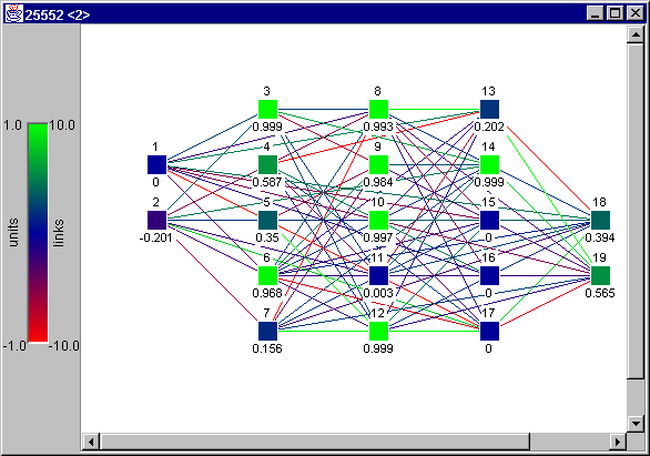
Network Creation and EditingNetwork View and Display SettingsAlthough not necessary, it is recommended that a network view is open when creating and editing networks. Network view is opened through View/Network menu. The network view displays a visual representation of the network, which comprises of units and connections (links) between them. Units are drawn as colored squares with 16 pixels side length, and connections as colored lines. For both units and links the color represents a value: activation for units and weight for links. The colored bar on the left edge of the network view serves as a quick reminder for color-to-value correspondence. (Figure 2) Units are placed along an invisible grid in the network view. Optionally, above and below each unit diverse unit properties can be displayed. Which ones, as well as grid size, chroma coding for units and links and some more data are set in the Display Settings panel, accessible from the View menu. This panel corresponds to the Display/Setup panel in SNNS. Display Settings comprise of two tabs: General and Units&Links (or SOM for Kohonen tool). In tab General, grid size (in pixels), subnet number and chroma codes for different values can be set. In Units&Links, the user can set which properties, like name, unit activation etc. are to be shown above (Top label) and below (Base label) of each unit. Also, the user can decide if the connections are to be shown, if their weights are to be displayed numerically and if the direction arrows should be drawn. Sliders "Maximum expected value" and "Maximum expected weight" control the chroma coding for units and links, since they determine which value corresponds to the full color, as set in the "General" tab. Minimum values are simply taken to be negatives of the maximums, and for values between the color is interpolated. The Slider "Weakest visible link" is self-explanatory and helps keeping the network view more comprehensible. 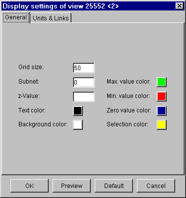
Figure 3: Display Settings - General 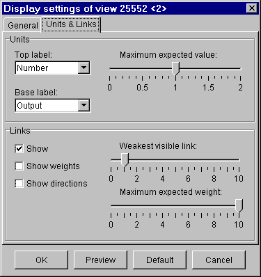
Figure 4: Display Settings - Units and Links Since more than one network view can be open at the same time, Display Settings refer to the currently selected one. Tools for Creating NetworksNetworks are created using two tools from the "Tools" menu, both from the "Create" submenu: "Layers" and "Connections". They together correspond to the "Bignet" tool in SNNS. In JavaNNS layer has a different meaning as in the SNNS. In JavaNNS, layer corresponds to a physical layer of units that is being created. When creating layers, width and height determine the number of units in horizontal and vertical direction for the layer. Top left position is updated automatically, but can also be entered manually, and controls the layer's position in the display area. For all the data - width, height and coordinates of the top left position - the measuring unit is "grid size unit", which is set in the View/Display Settings panel. In "Unit detail" segment of the window, the unit type (e.g. Input or Hidden), activation function of the units (Logistic by default), output function of the units (Identity by default), the layer number and the subnet number are set. The "Connections" window provides for creating links (connections) between units. Three different ways are possible for creating links: by manually selecting units to connect ("Connect selected units"), by automatically connecting the whole network in a feed-forward style ("Connect feed-forward") and by interconnecting those in the same layer (Auto-associative). In case of feed-forward networks, shortcut connections (links connecting units form non-adjacent layers) can optionally be created. For auto-associative networks, self-connections (feedback connections from the output to the input of a same unit) can be allowed. 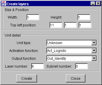
Figure 5: Create Layers tool Except for automatic generation of feed-forward connections, the user has to select units to be connected. Units are selected using the mouse, either by clicking each unit, or by clicking the mouse and dragging a rectangle around units to be selected. Units are deselected by clicking them while holding the CTRL key pressed. A simple click in an empty area in a network view deselects all units. Connecting selected units is a two-step process. In the first step, the user selects units where the connections are to originate (source units) and presses the button "Mark selected units as source". In the second step, the user selects the receiving units (targets) and presses the button, which is now labeled "Connect source with selected units". For auto-associative connections it suffices to select the desired units and press the "Connect selected units" button. 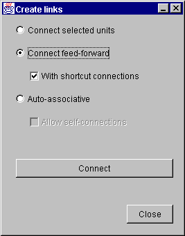
Figure 6: Create Links tool Selected units can be dragged with the mouse in order to change their positions. Editing UnitsExisting units can be edited by selecting them and then choosing Unit Properties from the Edit menu or Edit Units in the context-sensitive menu, which is accessed by pressing the right mouse button while over a unit. An extra window appears, displaying all editable unit properties, like name, type, activation etc. This method allows only for setting the same values for all selected units. Alternatively, the user can edit values displayed as top and base labels of each unit individually. For that purpose, the user has to choose from the Edit menu which property he or she wants to edit. The labels displaying the property turn to entry fields, which can now be edited. The fields are selected by the mouse and can be traversed by pressing the Tab key. Pressing Enter accepts changes and turns the fields back to labels. Changing activation values of units is useful if patterns are created manually. Last change: Igor Fischer, Thu May 16 14:13:36 2002 GMT Page 6: JavaNNS-manual-5.html |
