| HOME | CONTENTS | SLIDES | EXERCISES | ERRATA | REVIEWS | LINKS | CONTACT |
MIT Press ISBN-10:
0-262-06271-2 |
Exercises: Behavior-based Robotics |
|
Prerequisites
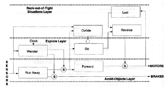
Overview The goal of this laboratory is to better understand the subsumption architecture (see this brief summary, if needed) by implementing a behaviour-based controller for a simulated industrial application, which would consist in transporting goods throughout a warehouse. This autonomous carrier must be able to follow some kind of track (e.g. a painted line on the ground), avoid obstacles found on its way and find its track again after disruption. To do so, we will implement this controller in a simplified scenario, on a small research robot: the e-puck. The "track" is embodied by a black line and the robot is equipped with color sensors oriented toward the ground. The objects to avoid are, e.g., cubic elements or simple paper cylinders. The robot is positioned on the line before the run. The robot must be able to follow the black line. Whenever an obstacle blocks its way, it must leave the line and follow the obstacle until it reaches the line on the other side. At this point, it must be able to recover its initial behavior by following the line towards the goal. Here is a clip demonstrating this behaviour: Provided are some (partially) preprogrammed behavioral modules, which can be used as is or modified (see the comments in the code for details):
One possible arrangement of those modules into layers (without the links) is given in this document. Your job consists of organizing these behavioral modules into a subsumption architecture (see Figure 1) by programming the links among them. Of course, you can implement your own modules, if you find the provided one not suitable.
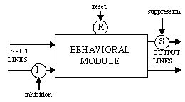
The following mechanisms (see Figure 2) can be used within your subsumption-like controller:
Software & programming environmentAs testing environment, we will first use the robot simulator Webots™ from Cyberbotics. If a good overall behavior is obtained in simulation then the behavior-based (BB) controller can be adapted and tested on a real e-puck robot. The required software are (1) Webots, and (2) a C compiler. Webots can be downloaded here. To launch Webots and prepare it for your application, follow these steps:
Note: do not change the name of the e-puck_line folder or of the file itself. Indeed, it is recommended to make backup copies of the e-puck_line.c controller by copying and renaming it in the same directory. Finally, in order to learn how to interact with the simulator (change view, zoom in and out, etc.), have a quick look at the section 2.3 of the User Guide (reachable via the Help menu in Webots or by pressing F4). The e-puck robotIn addition to the standard base and its 8 infrared proximity sensors (numbered from 0 to 7 starting from the front-right), it is equipped with three gray-level sensors (numbered from 0 to 2, starting from the left) oriented toward the ground. The simulated robot is a quite accurate copy of the real one. The sensor ranges as well as the motor commands are approximately respected. White noise is added at different level to improve the "simulated reality". A special library (embodied by a popup window entitled "e-puck"), is provided with Webots that allows for switching between simulation and reality (an e-puck robot must be connected on a Bluetooth virtual serial port). The same "e-puck" window displays the sensor and motor values in simulation as well as in reality. Coding the behavior-based controllerFirst you should have a close look at the provided code (webots/controllers/e-puck_line/e-puck_line.c) and try to understand how it works and how the behavioral modules are implemented. Then, before trying to make the connections between the modules, take a piece of paper or print this sheet and prepare an outline of your architecture (see Figure 1 & 2 above). Each of the links between the modules must be a clearly named variable. For sake of simplicity, we suggest to use global variables for this purpose. |